The Thin Lens Equation and Magnification
Image Formation by Thin Lenses
How does a lens form an image of an object? We can use the technique of ray tracing to illustrate how lenses form images. We can also develop equations to describe the images quantitatively. Recall the five basic rules of ray tracing:
- A ray entering a converging lens parallel to its axis passes through the focal point F of the lens on the other side.
- A ray entering a diverging lens parallel to its axis seems to come from the focal point F.
- A ray passing through the center of either a converging or a diverging lens does not change direction.
- A ray entering a converging lens through its focal point exits parallel to its axis.
- A ray that enters a diverging lens by heading toward the focal point on the opposite side exits parallel to the axis.
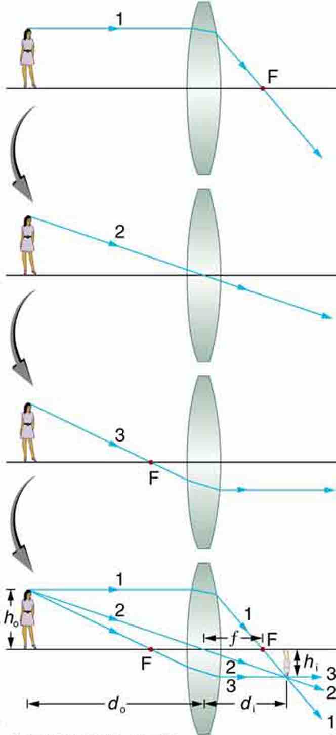
Consider an object some distance away from a converging lens, as shown in . To find the location and size of the image formed, we trace the paths of selected light rays originating from one point on the object (in this case the top of the person's head). The figure shows three rays from the top of the object that can be traced using the five ray tracing rules. Rays leave this point going in many directions, but we concentrate on only a few with paths that are easy to trace. The first ray is one that enters the lens parallel to its axis and passes through the focal point on the other side (rule 1). The second ray passes through the center of the lens without changing direction (rule 3). The third ray passes through the nearer focal point on its way into the lens and leaves the lens parallel to its axis (rule 4). The three rays cross at the same point on the other side of the lens. The image of the top of the person's head is located at this point. All rays that come from the same point on the top of the person's head are refracted in such a way as to cross at the point shown. Rays from another point on the object, such as her belt buckle, will also cross at another common point, forming a complete image, as shown. Although three rays are traced in , only two are necessary to locate the image. It is best to trace rays for which there are simple ray tracing rules. Before applying ray tracing to other situations, let us consider the example shown in in more detail.

Image Formation with a Thin Lens
Ray tracing is used to locate the image formed by a lens. Rays originating from the same point on the object are traced—the three chosen rays each follow one of the rules for ray tracing, so that their paths are easy to determine. The image is located at the point where the rays cross. In this case, a real image—one that can be projected on a screen—is formed.
Several important distances appear in . We define do as the object distance—the distance of an object from the center of a lens. Image distance diis defined as the distance of the image from the center of a lens. The height of the object and height of the image are given the symbols ho and hi, respectively. Images that appear upright relative to the object have heights that are positive and those that are inverted have negative heights. Using the rules of ray tracing and making a scale drawing with paper and pencil, like that in , we can accurately describe the location and size of an image. But the real benefit of ray tracing is in visualizing how images are formed in a variety of situations. To obtain numerical information, we use a pair of equations that can be derived from a geometric analysis of ray tracing for thin lenses. The thin lens equation is:
We define the ratio of image height to object height (hi/ho) as the magnification m. The magnification is related to do, di, ho, and hi by the following relation:
In many cases both of these equations are referred to together as the thin lens equations. The thin lens equations are broadly applicable to all situations involving thin lenses (and "thin" mirrors).