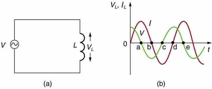
Suppose an inductor is connected directly to an AC voltage source, as shown in . It is reasonable to assume negligible resistance because in practice we can make the resistance of an inductor so small that it has a negligible effect on the circuit. The graph shows voltage and current as functions of time. (b) starts with voltage at a maximum. Note that the current starts at zero, then rises to its peak after the voltage driving it (as seen in the preceding section when DC voltage was switched on).

AC Voltage Source in Series with an Inductor
(a) An AC voltage source in series with an inductor having negligible resistance. (b) Graph of current and voltage across the inductor as functions of time.
When the voltage becomes negative at point a, the current begins to decrease; it becomes zero at point b, where voltage is its most negative. The current then becomes negative, again following the voltage. The voltage becomes positive at point c where it begins to make the current less negative. At point d, the current goes through zero just as the voltage reaches its positive peak to start another cycle. Hence, when a sinusoidal voltage is applied to an inductor, the voltage leads the current by one-fourth of a cycle, or by a 90º phase angle.
Current lags behind voltage, since inductors oppose change in current. Changing current induces an emf . This is considered an effective resistance of the inductor to AC. The rms current Irms through an inductor L is given by a version of Ohm's law:
Phasor Representation
The voltage across an inductor "leads" the current because of the Lenz's law. Therefore, the phasor representing the current and voltage would be given as in . Again, the phasors are vectors rotating in counter-clockwise direction at a frequency

Phasor Diagram
Phasor diagram for an AC circuit with an inductor.